Highly Precise and Low Power CW Radar System for Industrial and Medical Sensing Applications
Due to the decreasing costs and size of radio frequency (RF) components, radar systems have become very attractive for several applications in many different fields. Moreover, combining high resolution, low power consumption and operation in harsh environments makes them outperform conventional sensors. In this article, a radar system is presented that is developed with a low power transceiver at its core. This system is designed to show the usability for industrial as well as medical applications with a radar system at the 24 GHz industrial, scientific and medical (ISM) band. The review is based on the IEEE Microwave Magazine article [1].
If you want to know more about the radar technology developed by Sykno for highly accurate determination of vital signs and heart sounds, feel free to take a look at this new blog post or the YouTube video.
Radar-based remote sensing
Today, two main sectors of applications are the driving forces of sensor development:
On the one hand, there is the increasing research on industrial sensor systems. This evolution is furthermore driven by the digitization of production in different industrial environments and smart factories, which is commonly known as Industry 4.0, meaning the forth revolution of the industry after the steam engine, mass production and automated production. Therefore, it is more and more necessary to receive as many measurands as possible to increase the data generation and thus the information that can be gained by machine learning algorithms. In this environment radar technology offers many advantages over common sensors that are used for maintenance purposes. Radar systems can be easily hidden by radoms, penetrate fog and dust and are consequently applied in even the harshest environments to monitor different kinds of machines regarding their vibration or displacements.
On the other hand, there is the medical or lifestyle sector where radar and high frequency technology makes the difference. Without high signal processing efforts the radar system can be used for simple presence surveillance or, due to the very high resolution, even for vital parameter sensing. This means that the small movements that are caused by the respiration or heart beat on the surface of one’s chest are strong enough to be detected contactlessly by radar systems. Thus, applications can be:
- Driver surveillance
- Sleep monitoring of babys
- monitoring of employees
Due to the massive integration of high-frequency circuits in monolithic microwave integrated circuits (MMICs) in the last years, these radar systems for the above mentioned purposes can be built very compact, low-cost and by using programmed duty cycling of all active components very low power at the same time. In the following, a high-performance and low power radar system is described which can be used in industrial as well as medical and lifestyle scenarios.
Radar basics
State-of-the art radar systems can be grouped into two major categories depending on the transmit waveforms which are used. If an unmodulated sinusoidal signal is used, it is commonly called a continuous wave (CW) radar. If phase, amplitude and/or frequency of the sinusoidal change over time, the system belongs to the second group of modulated radars. Especially in the automotive industry, the frequency modulated continuous wave (FMCW) is widely used.
Frequency modulated continuouswave (FMCW) radars
A common group of radar systems transmit a modulated sinusoidal wave, for example a linear frequency chirp in so-called FMCW radars. Due to the bandwidth of the signal, the absolute distance between target and radar can be measured. The resolution mainly depends on the parameters of the frequency chirp, i.e. bandwidth and chirp duration. A phase evaluation can further be done to precisely monitor small displacements. However, the large signal bandwidth (usually several MHz) requires high sampling rates and a complex hardware setup.
Continuous-wave (CW) radars
In many industrial applications as well as in vital parameter sensing, presence detection and vibration analysis, a measurement of the displacement is sufficient. In these cases, the absolute distance between system and target is not of interest, while a highly precise measurement of the relative displacement around a zero point is desired. Therefore, an unmodulated sinusoidal signal with frequency \(f\) is transmitted and reflected by the target. At the receiver, the phase difference \(\Delta\varphi\) between transmit (Tx) and receive (Rx) signal is evaluated. Since it is directly related to the path delay of the electromagnetic wave by \(\Delta\varphi = 2\pi f \cdot \tau\) the displacement \(\Delta x\) can be determined if the speed of light \(c\) is known: $$\Delta x= c \cdot \frac{\tau}{2} = c \cdot \frac{\Delta\varphi}{4 \pi f}$$
In free space applications, \(c\) equals the vacuum speed of light. The factor of two in the equation appears due to the fact that a target displacement by \(\Delta x\) delays both the path from antenna to target and the path from target to antenna. In practical applications, the wavelength (for example 12.5mm at 24 GHz) is much smaller than the absolute distance between system and target and therefore an unknown number of sinusoidal periods occurs between Tx and Rx signal, making an absolute ranging impossible.
However, thanks to the theoretically infinitely small bandwidth of the RF signal, the required bandwidth at the receiver only depends on the speed \(c\) of the moving target, i.e. the occurring Doppler shift. The minimum required bandwidth can be estimated by $$B_\text{min}=\left(\frac{1+\frac{v}{c}}{1-\frac{v}{c}}-1 \right) \cdot f \approx \frac{2vf}{c}.$$
Thus, for a target movement of 1 m/s, a bandwidth of only 160 Hz is sufficient, if a 24 GHz Tx signal is used. The narrow signal bandwidth is a clear advantage of CW radars, since the noise power can be reduced by appropriate filtering and thus leads to a high measurement precision. Moreover, low sampling frequencies lead to low data rates and allow for power- and resource efficient systems. Since no modulation is required, the hardware effort is also small which leads to cost-efficient solutions.
After all, it can be stated that the system topology, with a modulated or unmodulated carrier, strongly depends on the application. A careful trade-off between features and performance has to be made leading to a tailored system for a given scenario.
In this article, a system for vibration analysis is presented. Since a high measurement precision is necessary, a CW system topology was chosen. It leads to a very compact, cost-efficient and lightweight solution to the measurement task.
Featured system
The following part is divided in an overview of the system and the concept that is used. In the second section the realization and the hardware demonstrator are presented.
Concept
The proposed system is designed to show the application of radar systems in different scenarios. In this paragraph the building blocks of firmware, RF and baseband are described.
For many applications a high sampling rate might not be necessary but a low power consumption is required. Therefore, the firmware is designed to be adjustable for this case. Since all active components as phase-locked loop (PLL), transceiver, temperature-compensated crystal oscillator (TCXO) and analog amplifiers are integrated in the system in a way that they can be shut down, a high percentage of power can be saved. This principle is called duty-cycling, which means that the microcontroller powers up all active components in the right order to perform the measurement and switches them off immediately afterwards. Shortly after, the microcontroller enters its sleep mode and wakes up again by an internally generated timer interrupt. Consequently, the power consumption is reduced tremendously and the resolution is still the same as in continuous mode. However, keeping Nyquist theorem \(f_\text{sampling}>2f_\text{max}\) in mind, the frequency of the duty cycling should not fall below two times the maximal expected frequency which is generated by the targets vibrations.
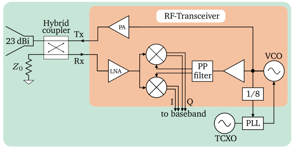
As a first part of the hardware, the RF section is explained in detail, as a crucial part of the overall system. The block diagram is depicted in Figure 1. One main component is the the used 24 GHz ultra-wideband transceiver. In this system the bandwidth is a parameter of freedom to find the ideal matching of the used innovative RF transition from microstrip to waveguide which is necessary for the used 3D-printed horn antenna. The output frequency is internally generated by a voltage controlled oscillator (VCO) which is locked by an external PLL, the ADF4158. The PLL receives the fed back and by 8 divided output signal of the VCO and compares it to a known reference which is derived from a TCXO, a temperature stable frequency source.
The output power of the signal can be easily increased by the integrated power amplifier (PA) which adds 4 dBm. This consequently increases the signal-to-noise ratio (SNR) and thus leads to a higher overall precision of the measurement. However, this of course increases the power consumption as well. The RF signal afterwards passes an external hybrid coupler since in this case a monostatic approach is pursued. This means that the same antenna is used for the transmission and receiving path. On the one hand, this reduces cost and size of the system but on the other hand the overall performance depends on the quality of the radar coupler, which cannot be seen as ideal in a real system. As an antenna, a 3D laser-sintered horn antenna is used. The weight is reduced by more than 30% due to the included holes with a diameter small enough to have no influence on the propagation of the electromagnetic wave. The backscattered signal is then guided in the receiver path and inside the transceiver. Before performing the down conversion, the SNR can be further increased by switching on the integrated low noise amplifier (LNA). Finally, four down converted DC voltages are generated and form the differential IQ signal. By using differential signals, the system becomes more tolerant against common mode interferences.
In the next part, the analog baseband circuit is investigated more precisely. The circuit is shown in Figure 2 and is separated in two parts outside and inside of the used microcontroller STM32F373.

The figure shows the circuit for the I or Q channel and starts with a fully differential amplifier which amplifies the signals and still remains the differential behavior. This helps to avoid common-mode distortions and hence optimizes the SNR. Afterwards, a passive low-pass filter is applied to suppress high frequency signal components. However, the filter has to be designed such that the short DC pulses, caused by the duty-cycling and the short RF pulses are still able to pass this filter and are not suppressed. This trade-off between bandwidth and settling time is a key factor for these kind of radar systems. Inside of the microcontroller the differential signals can be further amplified by a programmable gain amplifier (PGA), before being digitized with the integrated 16 bit sigma-delta ADC. The I and Q data is finally transmitted via an FTDI-Interface and universal serial bus (USB) to the host PC where the data is processed in Matlab.
With $$\Delta\varphi=\arctan\left(\frac{Q}{I}\right)$$ the phase difference can directly by calculated. From there on, the relative displacements of the target can be calculated with the already mentioned equation \(\Delta x= c \cdot \frac{\tau}{2} = c \cdot \frac{\Delta\varphi}{4 \pi f}\). After these basic operations a fast Fourier transform (FFT) is applied to calculate for example the vibration frequency of the target or the heart and respiration frequency of a person.
Hardware-Demonstrator
This section describes the hardware demonstrator that is shown in Figure 3. The circuit is developed on a four layer stack-up with RF cores made of Rogers RO4350B material. Especially for a high production volume, this stack-up is very low-cost at a still excellent performance. However, to realize the novel transition between the microstrip andwaveguide WR42 blind vias have to be applied. The used transition is presented in [2] and has the advantage that the antenna can be mounted on the back of the printed circuit board (PCB). Due to that, backscattered signals hardly can couple into the resonant structures of the hybrid coupler on the front which further improves the performance especially for very low displacement amplitudes. The antenna itself is designed as a horn antenna with a gain of 23 dBi and matches the simulations very well for a laser sintered manufacturing process. For applications that require a smaller antenna, a patch array as presented in [3] or smaller horn antenna may be applied. The key is to always find the right trade-off between the necessary performance and size or weight.

By looking at the PCB of the demonstrator the separation of digital, analog and RF part of the circuit becomes apparent. This is also important to reduce effects of electro-magnetic interference (EMI) between digital and analog parts that can significantly decrease the signal quality. The overall weight without cables was measured to be 67 g and at a duty cycle of 19 samples per second (Sa/s) the power consumption is less than 10 mW. By reducing performance it is even possible to stay below 30 µW with a similar system as shown in [4].
Measurements
With the demonstrator shown in Figure 3, two measurements were performed to show the capabilities of RF sensor systems in industrial and medical applications. Both measurements where performed at the same distance and with the same sampling frequency of 0.8 m and 19 Sa/s, respectively.
The first one is an industrial scenario where a metallic plate with the size of 12 cm x 8 cm is placed on a linear stage at the defined distance in front antenna’s aperture. The stage is programmed to oscillate at an amplitude of only 5 µm and a frequency of 0.7 Hz. In Figure 4 the measured data is shown after digital filtering. It can be clearly seen that the measured amplitude matches the specified amplitude of the linear stage very well. Furthermore, an applied FFT in Matlab returns the exact adjusted frequency.
In a second measurement, which states an example for a medical application of radar sensor systems, a person is sitting at the same distance of 0.8 m in front of the antenna. The main lobe of the antenna points towards the chest of the person. After digital postprocessing the heart beats can be seen very clearly which is shown in Figure 5. An FFT determined the person’s heart rate at this point of time to be 62 beats per minute.


Conclusion
In this article, two major applications of radar sensors in industry and the health/lifescience sector have been presented.
In industrial applications, radar systems can be used to detect tiny displacements. This might be oscillations or vibrations of moving parts and machines. The frequencies and amplitues of these oscillations provide valuable information on the condition of the device, which helps to prevent faults and damages.
In the medical field, changes in heart and respiration rate can be monitored contactlessly. The data can be used to detect tiredness and mental stress of car or truck drivers. Moreover, high-risk patients, such as babys or sick people can be monitored continuously, without affecting the comfort or the daily life.
For both sectors the advantage of radar, that non-conductive materials as clothes, dirt, fog or even mattresses are penetrated is huge. Beside the mentioned applications a further almost infinite number of others are thinkable. Moreover, since the costs for components are rapidly decreasing and microcontrollers become even stronger calculation units, radar and RF systems are one of the key future technologies.
Are you interested?
You are interested in a tailored solution for the contactless measurement of vibrations or vital parameters? Get in touch with us and follow us on LinkedIn!
Further reading
[1]
B. Scheiner, F. Michler, F. Lurz, R. Weigel, and A. Koelpin, “Nothing Beats SNR: Single-Digit Micrometer Ranging Using a Low-Power CW Radar Featuring a Low-Weight 3D-Printed Horn Antenna”, IEEE Microwave Magazine, vol. 21, iss. 1, pp. 88-95, 2020.
[2]
E. Hassan, B. Scheiner, F. Michler, M. Berggren, E. Wadbro, F. X. Röhrl, S. Zorn, R. Weigel, and F. Lurz, “Multi-Layer Topology Optimization of Wideband SIW-to-Waveguide Transitions”, IEEE Transactions on Microwave Theory and Techniques, 2020.
[3]
F. Michler, B. Scheiner, F. Lurz, R. Weigel, and A. Koelpin, “(Micro)metering with Microwaves: A Low-Cost Low-Power High-Precision Radar System”, IEEE Microwave Magazine, vol. 20, iss. 1, pp. 91-97, 2019.
[4]
F. Lurz, F. Michler, B. Scheiner, R. Weigel, and A. Koelpin, “Microw(h)att?! Ultralow-Power Six-Port Radar”, IEEE Microwave Magazine, vol. 19, iss. 1, pp. 91-98, 2018.